
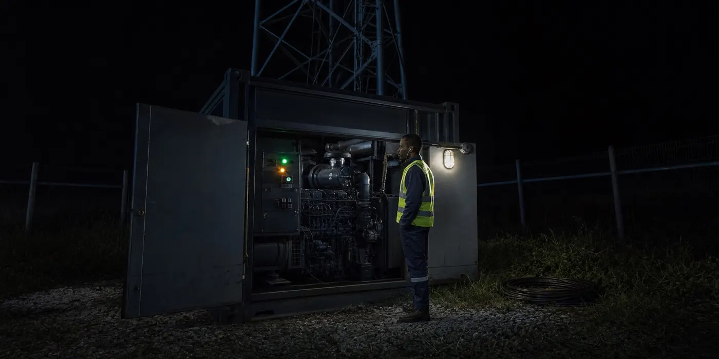
A generator monitoring project can range from a simple running/not-running input to a full controller integration carrying voltage, frequency, current, run hours, utility state and alarms. Those are different designs. The correct one depends on the controller model, available port, documentation, critical decisions and the team that will respond.
We start by separating four layers: the generator and sensors, the controller, the communications link, and the remote platform. Commissioning must prove the path end to end. A value visible on the controller screen is not necessarily available through its remote protocol, and a register visible remotely is not necessarily configured with the correct scale or alarm rule.
1. Begin with the operating decision
- Must the team know that the generator started, failed to start or stopped unexpectedly?
- Is utility availability required to explain why the generator ran?
- Which electrical or engine alarm needs an immediate escalation?
- Are run hours used to plan maintenance, reconcile fuel or verify a service visit?
- How long may a site remain offline before the event becomes critical?
Assign an owner, communication channel and response time to each selected event. If a register has no operational use, collecting it can wait. This keeps the first deployment testable and makes notification fatigue less likely.
2. Identify the controller and interface
Record the generator, engine and controller manufacturer, exact model, firmware version and fitted communication modules. The Deep Sea Electronics DSE7320 MKII, for example, is documented as an auto mains failure control module with monitoring, protection and communications capabilities. The specific manual and configuration still determine which measurements and interfaces are available.
Possible integration paths include dry-contact inputs, analogue signals, CAN, RS-232, RS-485, Ethernet or a manufacturer gateway. Do not assume two controllers with similar front panels expose the same protocol. Photograph the label, export the configuration where permitted, and keep the register documentation with the site record.
GT AFRIK reads DSE, ComAp and DATAKOM controllers over Modbus RTU through a Teltonika FMB125; the supported generator controllers list and the generator monitoring in DRC page give the details.
3. Map Modbus data precisely
Modbus defines application messaging used across serial and TCP communications. A working integration also needs the controller’s register map: address, function, data type, byte order, scale, units and valid range. Register numbering conventions can differ between documents and software, so the commissioning sheet should record both the documented reference and the address entered into the gateway.
On RS-485, confirm device address, baud rate, parity, stop bits, polarity, cable topology and termination. Avoid guessing when readings appear plausible. A wrong word order or scaling factor can turn a valid electrical value into a dangerous operating conclusion.
4. Choose a minimum useful signal set
| Decision | Candidate signals | Commissioning test |
|---|---|---|
| Confirm run state | Engine running, generator frequency or controller state. | Start and stop under controlled conditions; confirm timestamps. |
| Explain automatic start | Utility available, utility voltage and transfer state. | Simulate only under an approved safe procedure. |
| Plan service | Engine hours, start count and maintenance alarm. | Compare totals with controller and service record. |
| Escalate fault | Common alarm plus selected coded alarms. | Use controller test functions or an approved simulation. |
5. Turn alarms into a response workflow
Define severity, recipient, acknowledgement and escalation. A low-battery warning, emergency shutdown and communications loss should not follow identical paths. Include site identity, event time, last valid reading and controller alarm name. Avoid translating a manufacturer alarm into a stronger conclusion unless the technical mapping supports it.
6. Plan for power and connectivity loss
Remote sites may lose the same utility power and mobile connection that the system is meant to monitor. Document the gateway supply, backup duration, controller communications state and offline record storage. An offline alert should distinguish the last controller data from the last gateway heartbeat. When service returns, verify that stored events arrive in order and are not mistaken for new alarms.
For sites in the capital, the GPS tracking and generator monitoring in Kinshasa page explains monitoring during power cuts (délestages).
7. Preserve maintenance evidence
Run-hour totals become useful when tied to a declared source and service record. Keep commissioning values, replacements, controller resets and any manual correction. Review trends for impossible jumps, rollovers and long flat periods. Remote data can prioritise work, but site safety procedures and qualified inspection remain authoritative for maintenance action.